Making an Electric Longboard - Raw 18650 batteries and wood to road rash
Still working to edit this post…
A summary document detailing how I made my electric longboard
During my last few years in high-school, I became interested in electric power generation and transport. This was primarily due to an interest in Tesla and its impressive developments at the time. As a lover of hardware, I wanted to get more experience in the area, but I couldn’t afford a Tesla. I aimed lower and started looking into electric bikes. Then I realized I still couldn’t afford that project, so I aimed even lower and realized I was looking at my feet. A longboard! That’s what I’d build. They’re small, useful, and most importantly, transportable in my car to college.
I looked at previous successful projects on the internet and came up with a design I could build myself. The end result was a medium-sized longboard from a single piece of maple, dual hub motors, and a 2P10S (2 cells in parallel with 10 of those pairs in serial) batterypack composed of Samsung 18650 cells. From the research I did, this seemed to provide a low-cost yet performant electric longboard. Here was my materials list:
| Part | Price |
|---|---|
| 20 Li-ion Batteries | $75.00 |
| 0.15mm x 8mm Nickel Strip | $7.00 |
| Hub Motors | $150.00 |
| 10s Battery Charger | $26.00 |
| Skate Tool | $4.00 |
| Battery Charging Cable | $5.00 |
| ESC | $88.00 |
| 8pc Deck Hardware | $3.00 |
| 8mm Shokpad Risers | $4.00 |
| Bestech 10s BMS | $34.00 |
| Battery Volt & Temp Monitor | $17.00 |
| Battery Heat Shrink | $7.00 |
| DiyEboard Shipping | $38.00 |
| Total Cost | $458 |
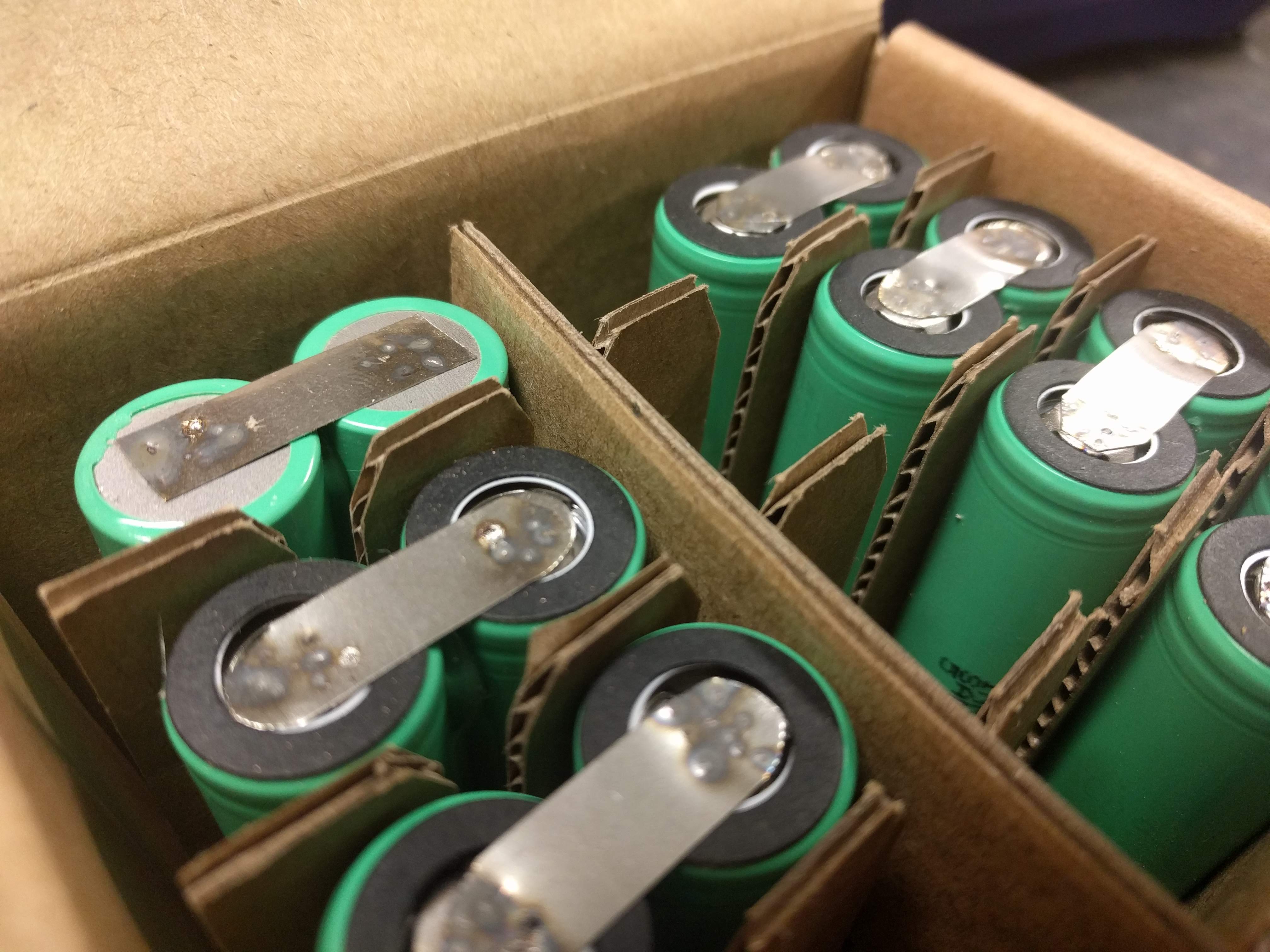
The first step was to build the battery pack. After reading about Tesla and Panasonic’s partnership in developing new batteries, it felt somewhat wrong to order 18650 cells and have them arrive at my door. I held some sort of reverence that building with raw cells was something you didn’t do unless you were in a commercial production environment. This project definitely shifted that perspective…which is exactly why I wanted to do it.
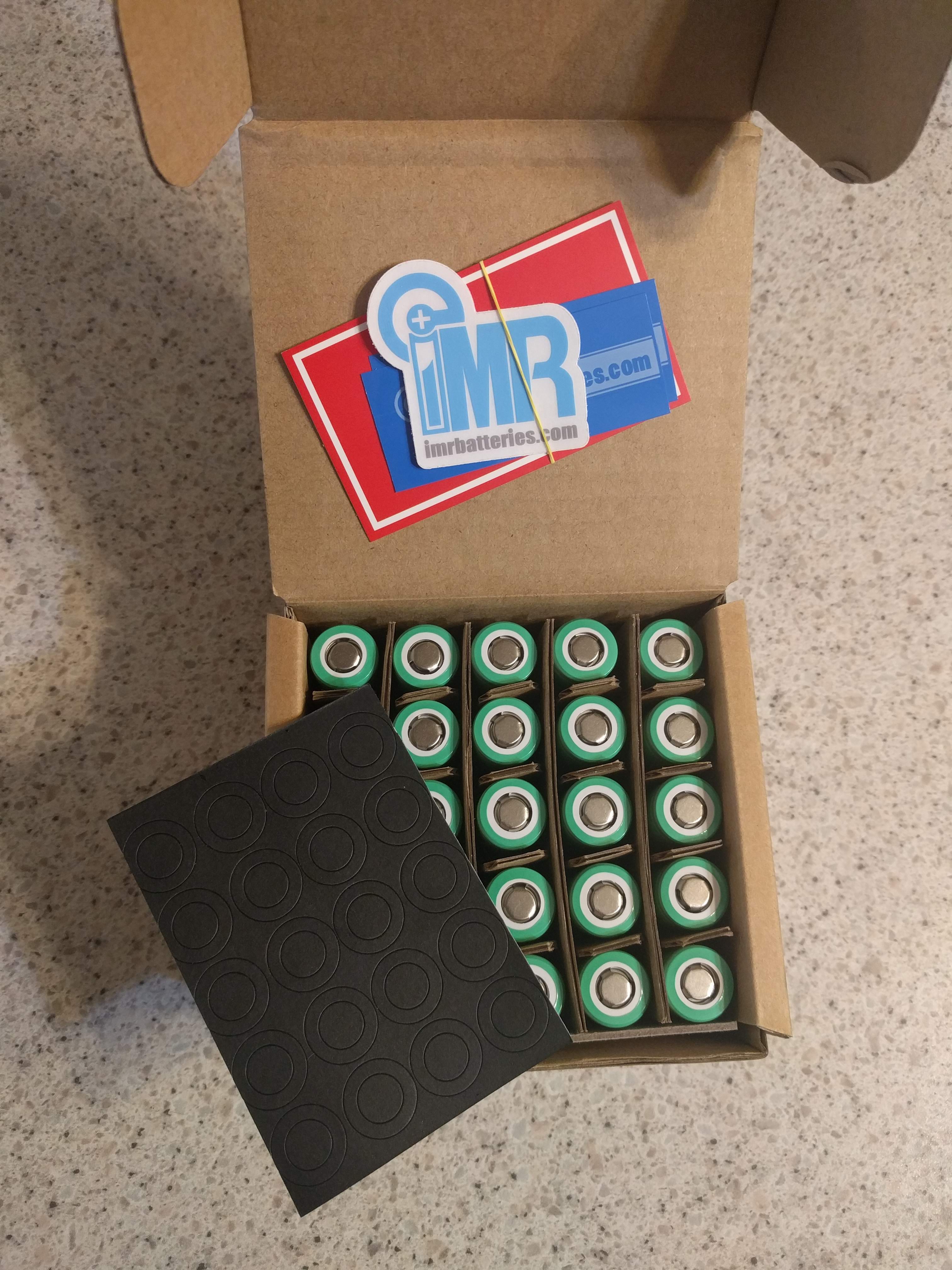
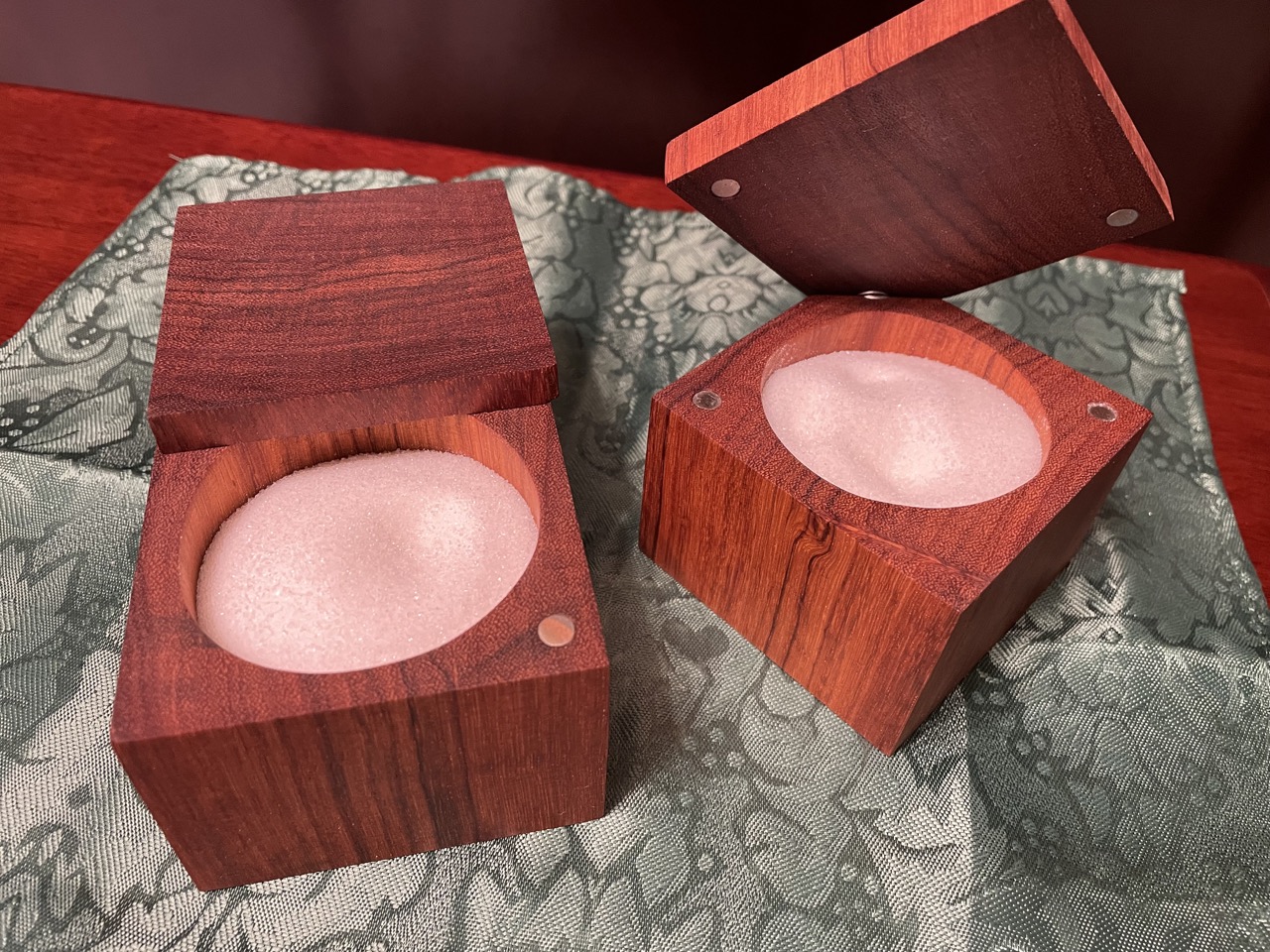
The Samsung 18650 cells as they came from the distributor
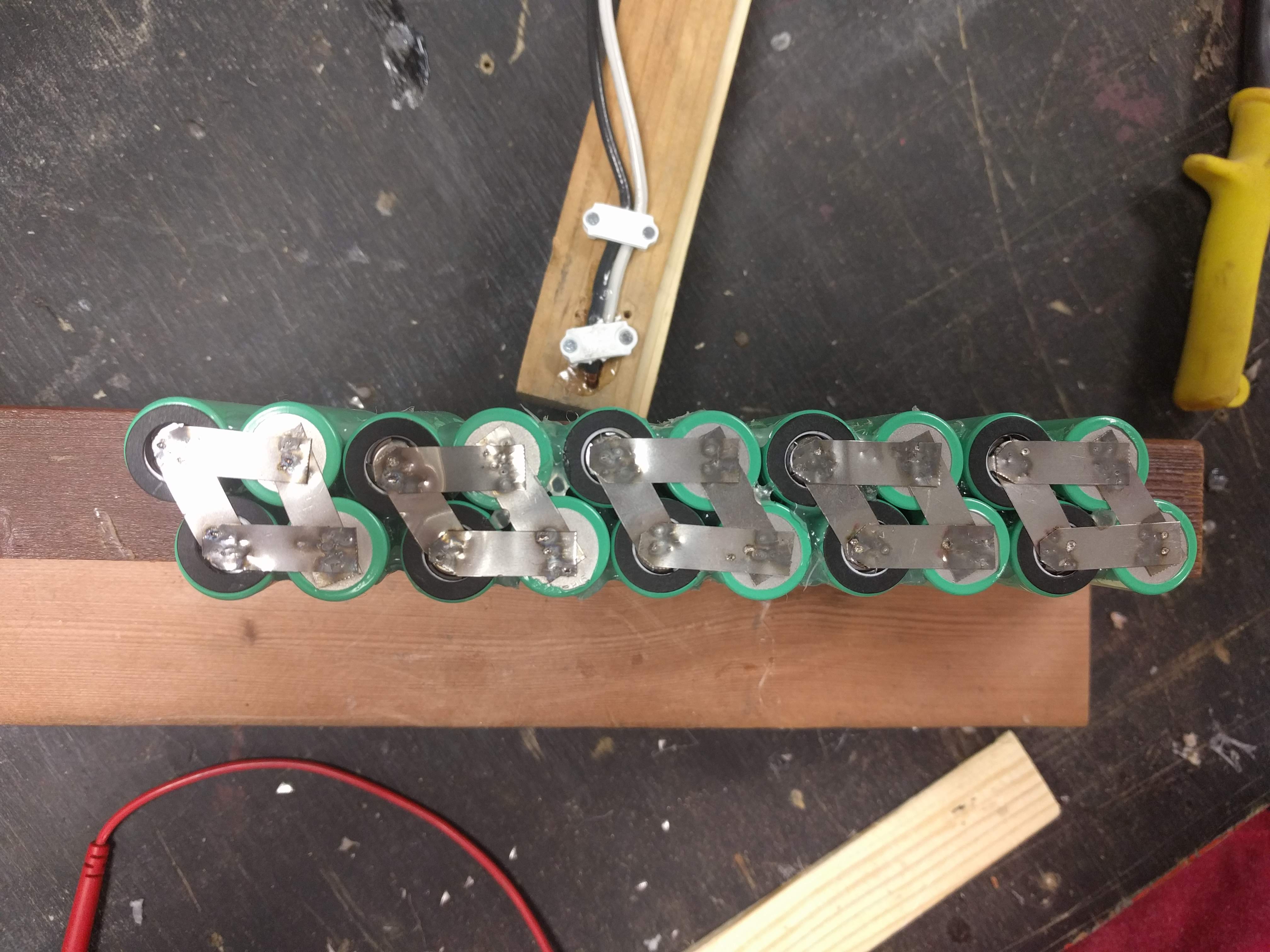
Once the raw cells arrived, they had to be spotwelded together. This is a different process than I was used to after only soldering components for all my previous electrical projects. These batteries can’t be soldered together because it would overheat the cells and not be a very secure connection. Spotwelding introduces less heat because of its more instantaneous nature. To spotweld these cells, I’d cut a length of pure nickel strip, place it on the battery terminals, then press two copper nail tips to the nickel strip. Next, I’d short a lawnmower battery to cause current to flow through the nickel strip between the copper terminals. This process heats up the nickel just enough to weld it to the battery terminal. I’d repeat this process twice per terminal/nickel strip interface and hot glue the adjacent cells for structural support.
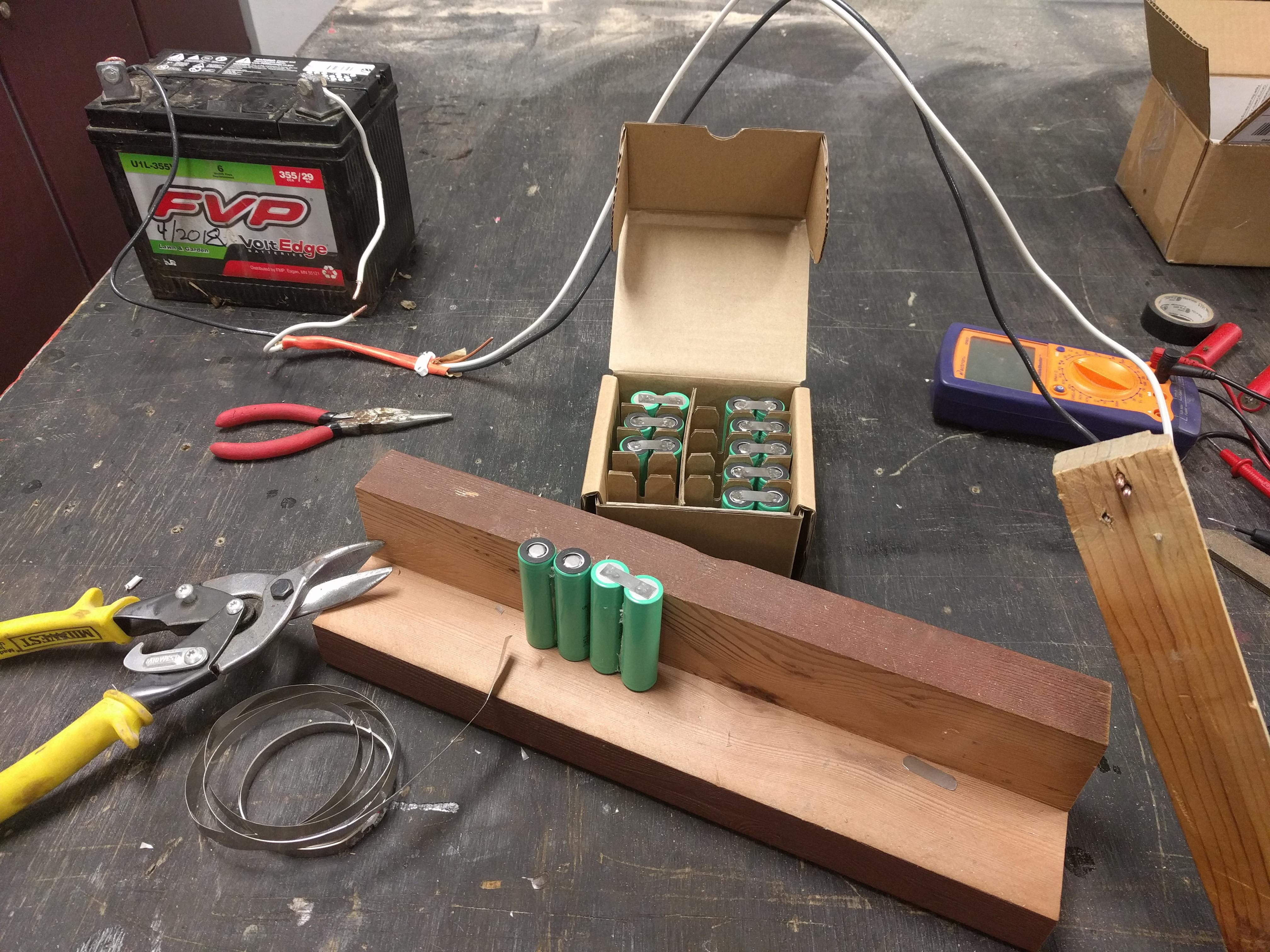
The spotwelding setup: a lawnmower battery, diy spotwelder terminals, nickel strips, and tin snips. Not pictured: ice cubes to put the terminals in after they heat up.
Clearly the setup wasn’t the most advanced. Because of the massive current passing through the circuit each cycle, the cables and nails would heat up. After 3 or so spotwelds, my dad (who helped short the battery while I held the terminals in position) and I would have to wait for the components to cool down - sometimes with the aid of an ice cube from our drinks. The heated copper had a higher resistance and would result in lower currents and thus bad spotwelds.
Once the cells were spotwelded and glued together to form the bare batterypack, I used my multimeter to check that the resultant output voltage was correct. After confirming this, I then carefully soldered the output battery leads and individual cell-pair leads for monitoring. Kapton tape (heat-resistant and electrically insulating tape) to further secure and protect the cell terminals. Then I connected the wires up to the power switch, battery management system (BMS), and temperature/voltage monitor and display.
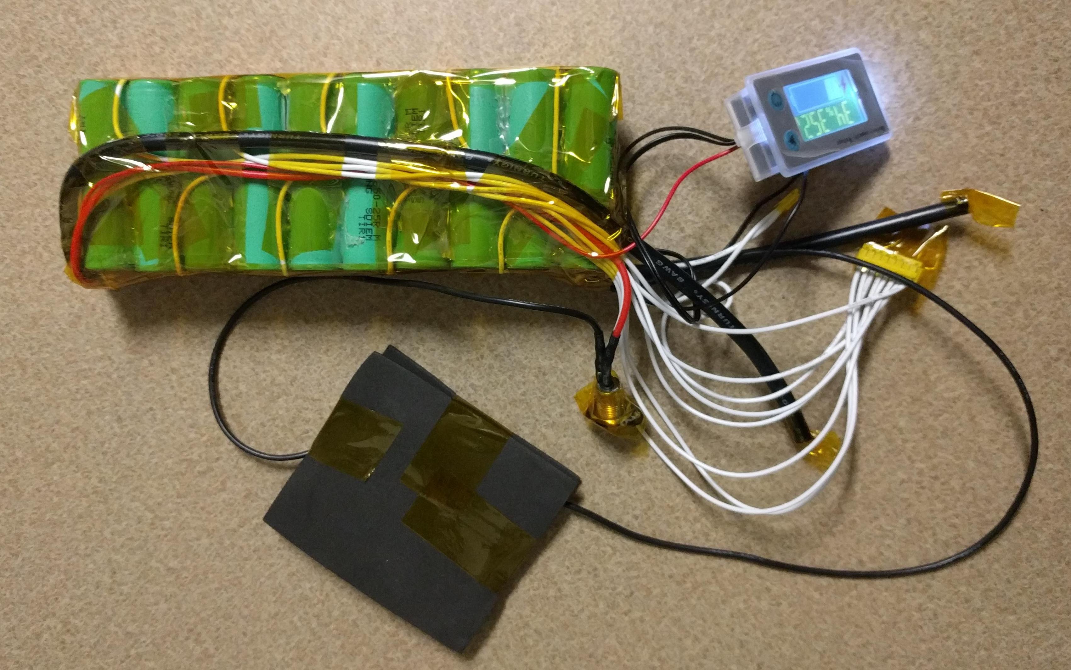
The assembled batterypack and monitoring electronics
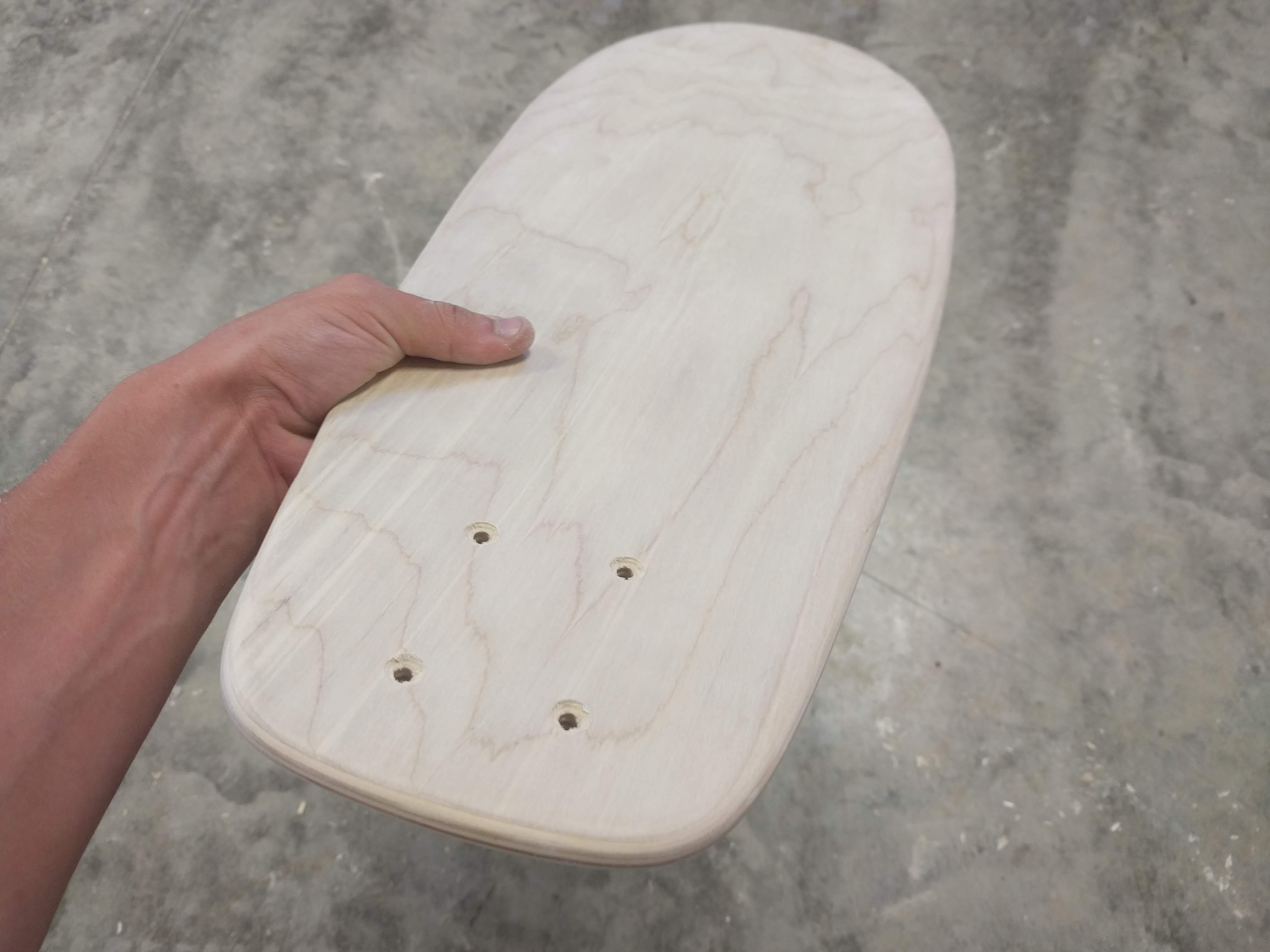
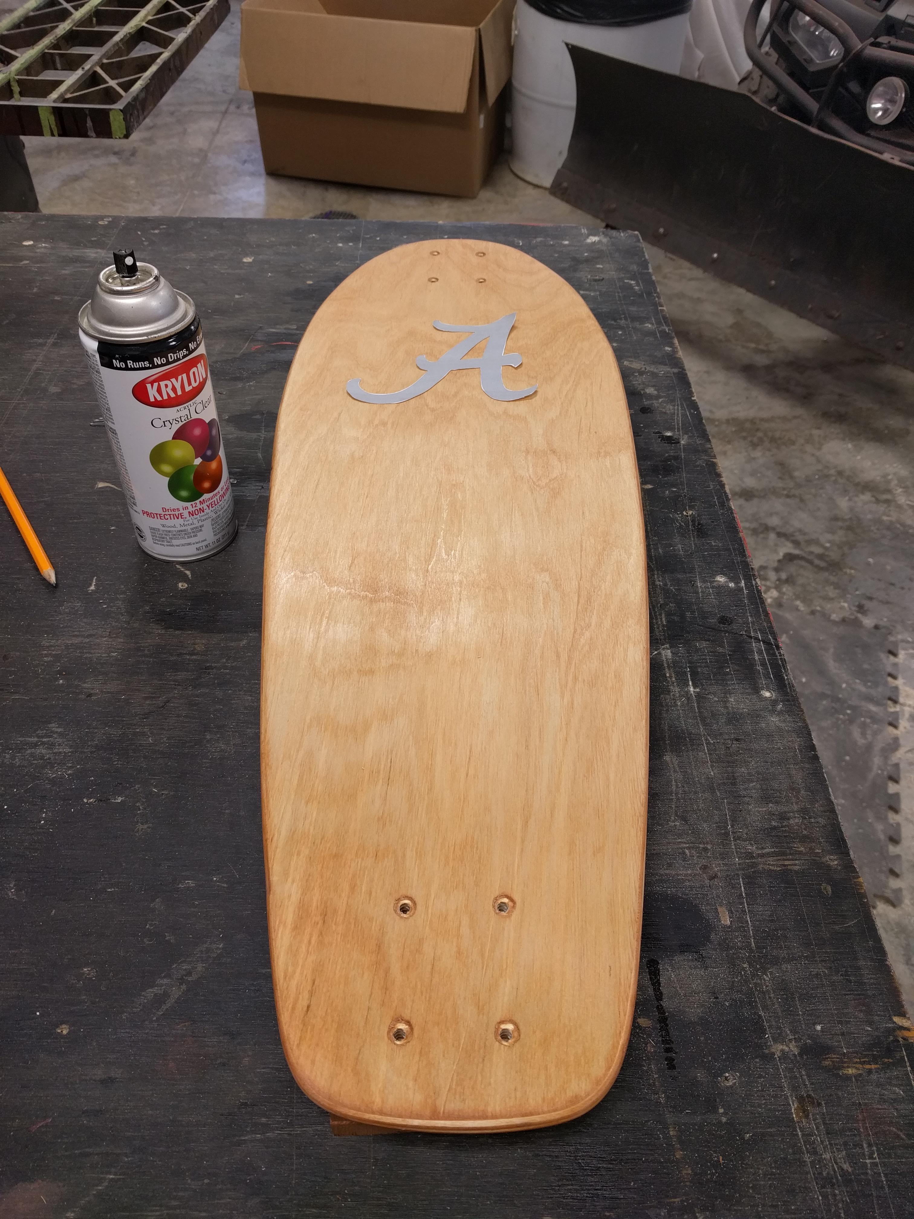
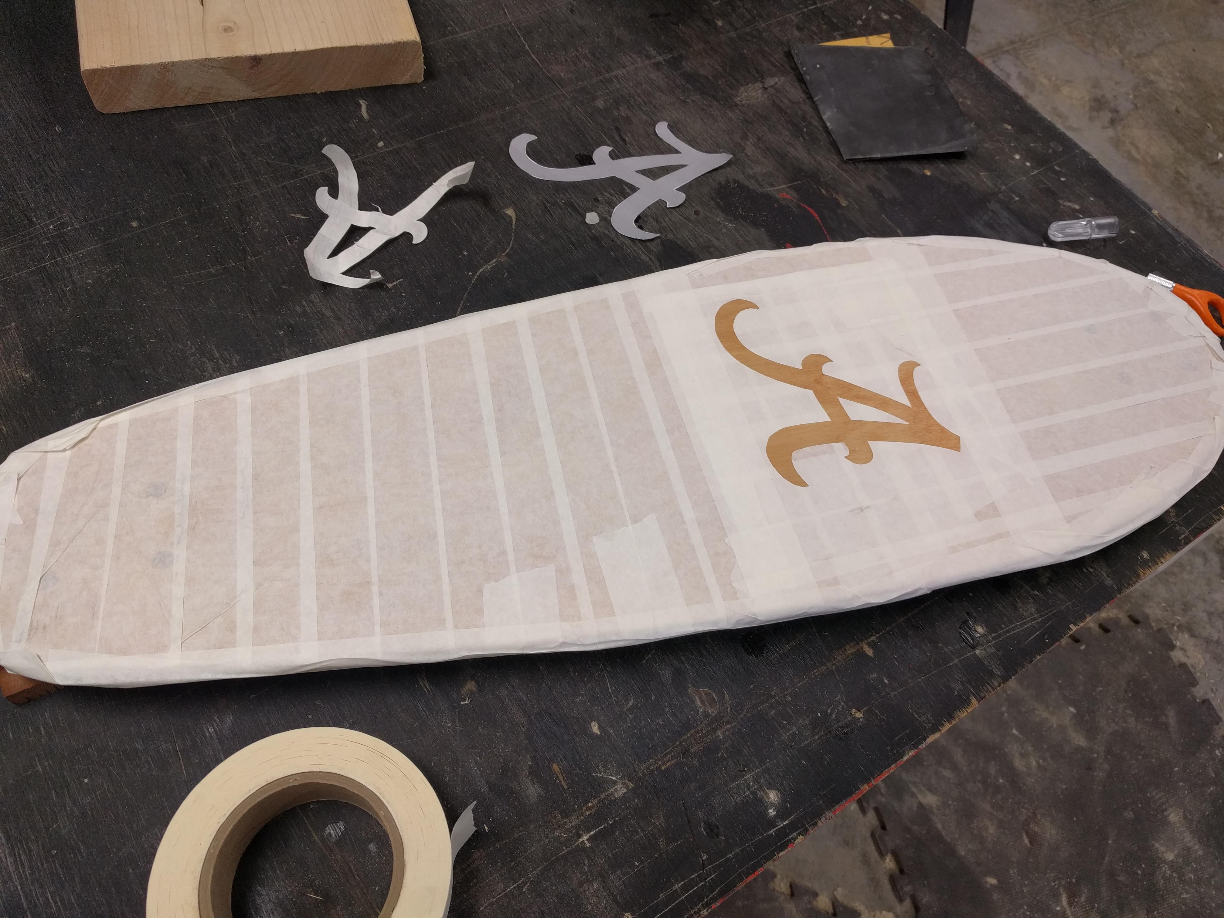
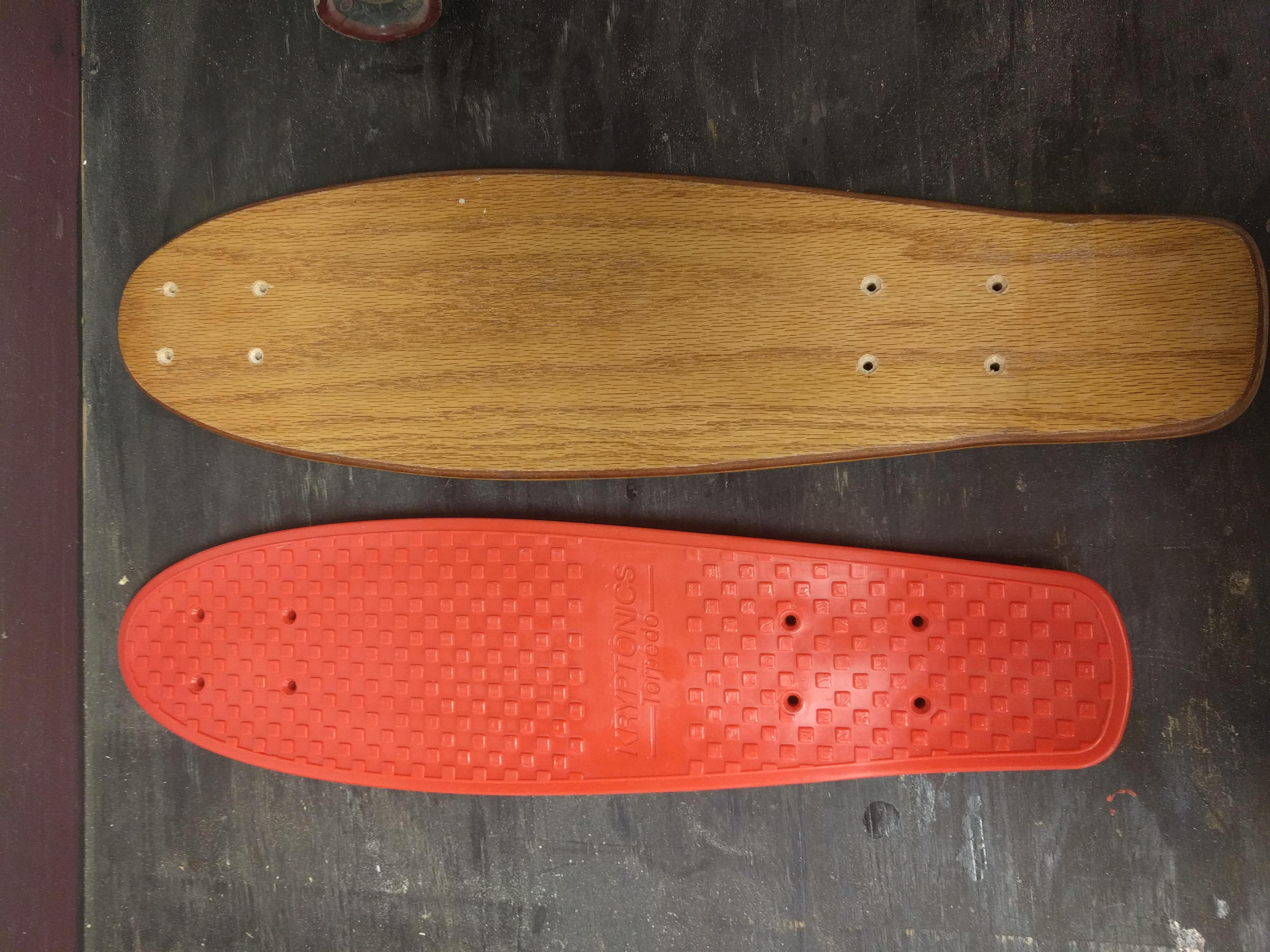
After the batterypack was at a safe state for storage, building the deck was next. It was made from a single piece of maple, so this part didn’t take too long but involved a few carpentry tools to make life easier. After experimenting with different deck sizes with simple paper sketches placed on the ground, I decided on a final design and traced it onto the wood. Then I used a jigsaw to cut out the rough shape, a hand sander to round the edges, a countersink bits for the deck hardware screw-holes, and simple elbow grease for final sanding. Afterwards, the deck was stained, painted with Bama’s script-A (Roll Tide!), and sprayed with sealant.
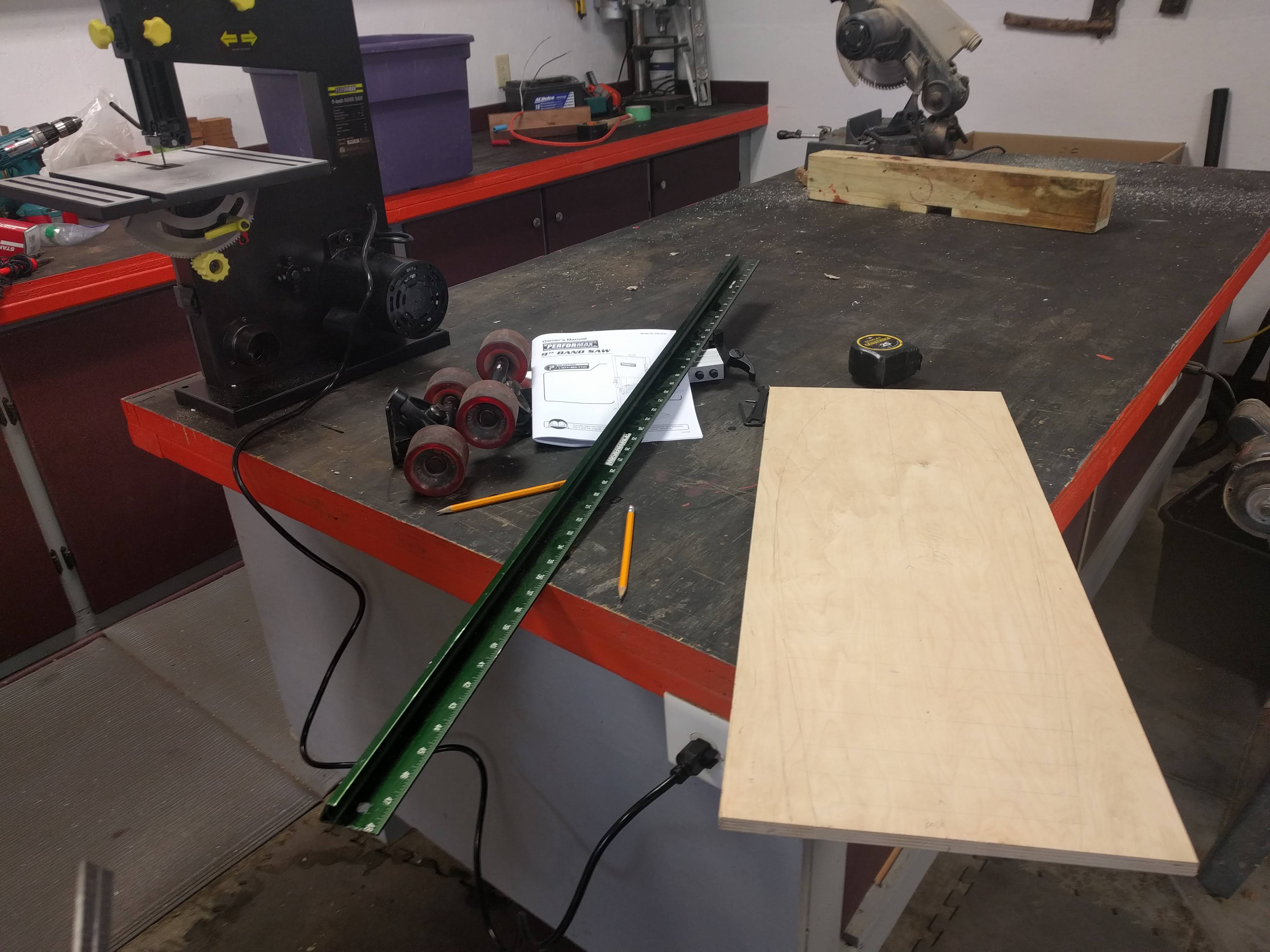
Non-electronic hardware
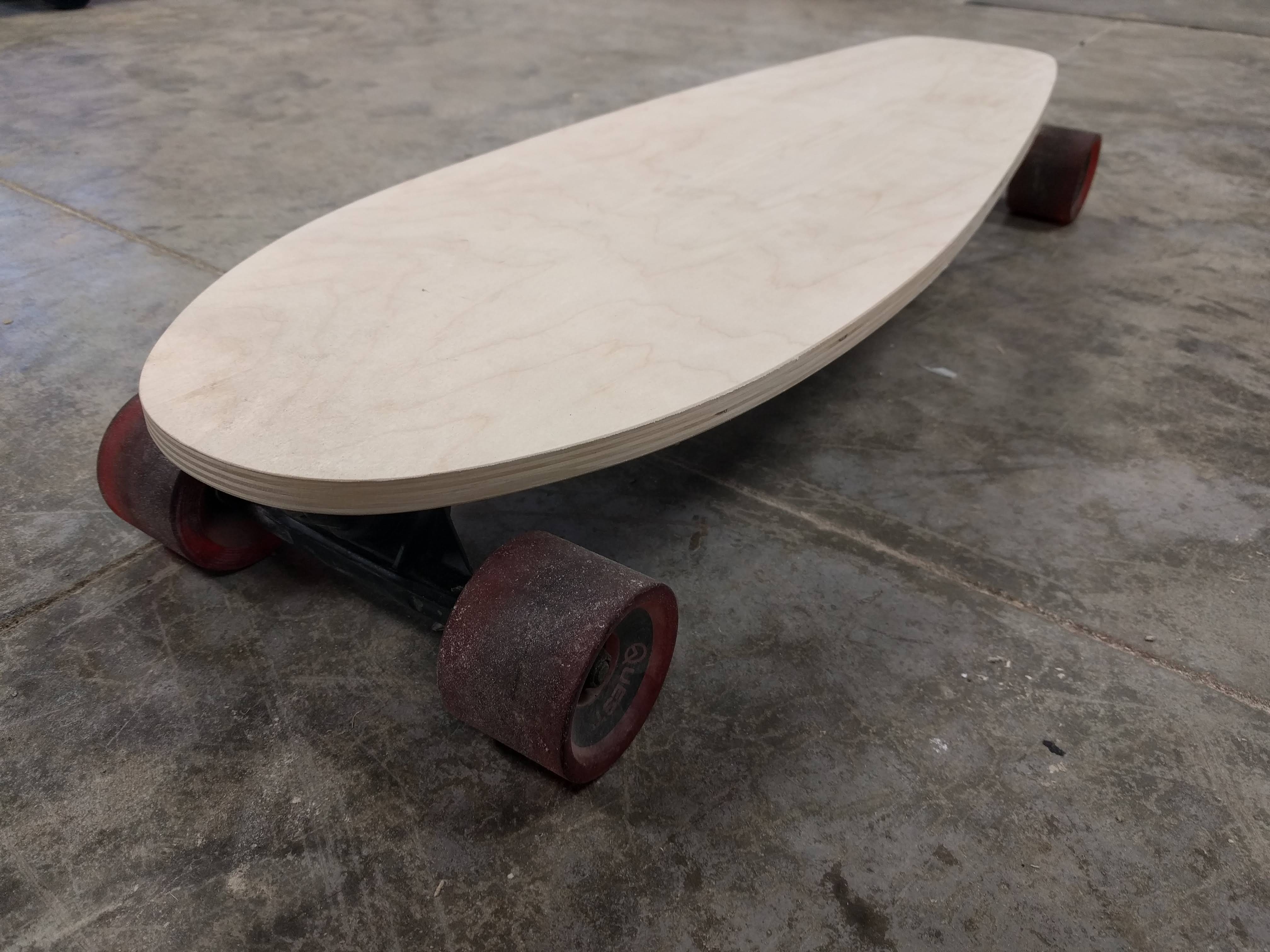
Rough longboard setup for initial size/ride testing
Here’s what the intermediate results were. Later, clear griptape was added for better traction.
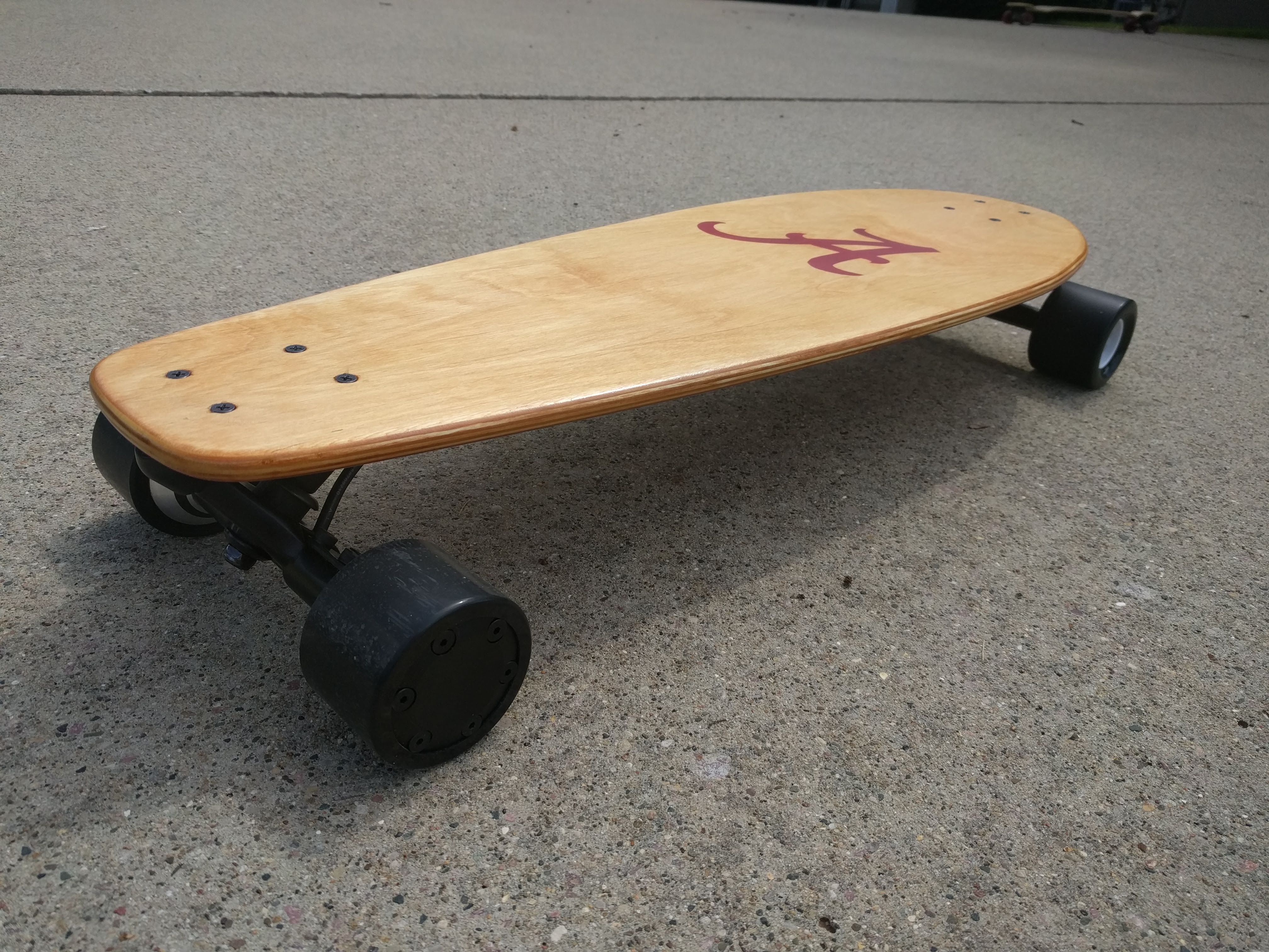
The assembled longboard without electronics
At this point, I took the longboard (currently without electronics) for a ride with friends to test it out and see how it rode. I was new to longboarding at the time, so I couldn’t judge the quality that well. I found it moved well but transmitted more road bump displacement to my ankles than I would’ve liked. That’s what happens when you have a single-piece, inflexible piece of wood for a deck though.
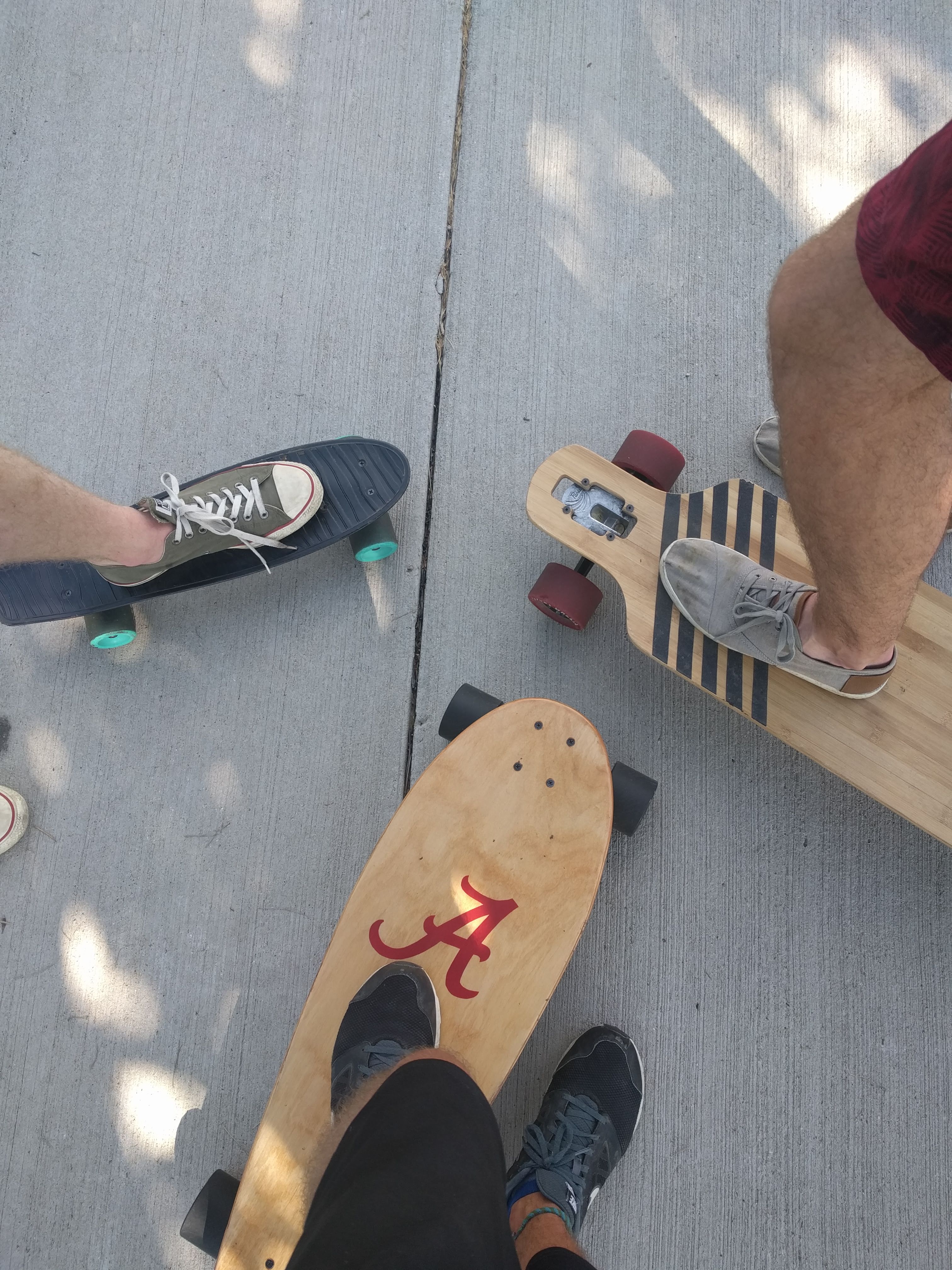
Riding the longboard with some friends before college
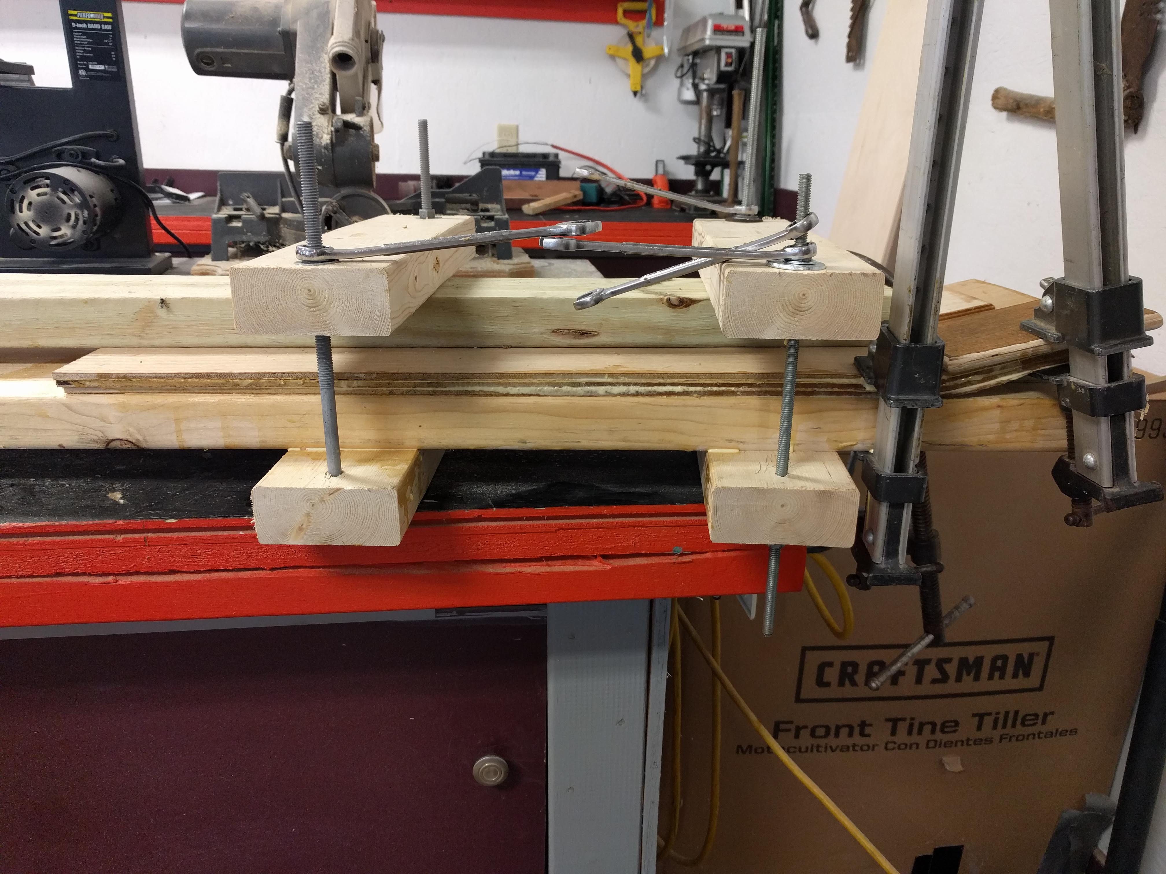
Pennyboard clamp system for an angled 'heel'
The assembled batterypack after protection added in my dorm
The clear Kydex enclosure prior to forming
DIY electronics support after Kydex forming failure
A video showing the longboard accelerating and decelererating during testing.

The outcome of testing...a good project has to result in injury at some point, right?